NOVA-C
The Room tab can only be accessed and edited with the Edit sensor area permission.
In the room tab, the room is configured and regions are created, if necessary.

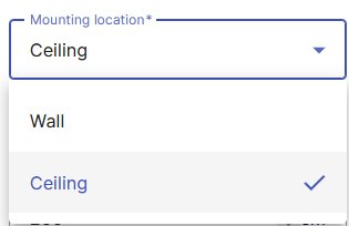
Mounting
Different parameters are available depending on the mounting location. The dimensions must correspond to the actual room so that the sensor works correctly and no false alarms occur.
It is advisable to define the room 10 to 20 centimeters smaller than it actually is in order to rule out possible interference from the wall.

Adjusting the dimensions will cause the outlined space to increase or decrease on the web page. This is intended to give a feeling for the detection area of the sensor.

Low wall mounting - wall at 1.5 m height
This is the standard way to mount a sensor on the wall using the 22° wall installation accessory at a height of 1.5 to 1.6 meters. This is the classic and simplest method of installation, but it has the disadvantage that falls behind larger objects (e.g., a table, sofa, or bed) may not be reliably detected.
When mounting on the wall, ensure that:
- the sensor is mounted on the 22° wall installation accessory and thus mounted to the wall.
- the power cable is directed downwards toward the floor, and the sensor is not rotated 90° or 180°.
- reliable fall detection cannot be guaranteed in the bathroom.
The attachment with adhesive or Velcro pads takes place on the side with the identification sticker.
|
Parameter |
Meaning |
|---|---|
|
Height above ground |
Information on the mounting height of the sensor above the floor. For the sensor to function correctly, it should be mounted at the standard height above the floor. |
|
Length |
Length of the room from the sensor to the opposite wall. |
|
Left |
Distance from the sensor to the left wall. The sum of the distance to the left and right walls must not exceed the maximum range. |
|
Right |
Distance from the sensor to the right wall. The sum of the distance to the left and right walls must not exceed the maximum range. |
To enter the length information, it is advisable to imagine that you are behind the sensor and are looking at the type plate / the Velcro strips. The power cable goes down to the floor, the button points up to the ceiling.
After changing options and values, save the page (at the bottom) so that the new settings are transmitted to the sensor. The transfer may take a few seconds.
Ceiling
For the best possible detection, it is important that the sensor is mounted correctly. The sensor must have a clear view of the room and can also better detect falls behind larger objects (e.g. table, sofa or bed).
It should be positioned as close to the middle of the room as possible, but at least 70 cm away from ceiling fans, lamps, smoke detectors or other devices or objects on the ceiling. These can impede the range of the sensor or interfere with its radio waves. The sensor must also be at least 50 cm away from the wall.
Mounting on the ceiling with adhesive or Velcro pads is done on the side with the identification sticker.
The device must be mounted completely flat on the ceiling.
|
Parameter |
Meaning |
|---|---|
|
Height above ground |
Specifies the mounting height of the sensor above the floor. The default value is 3.0 meters. |
|
Direction button |
Length of the distance from the sensor button end to the nearest wall. The sum of the distance towards the button and towards the cable must not exceed the maximum range. |
|
Direction cable |
Length of the distance from the sensor cable end to the nearest wall. The distance must not exceed 2 meters. The sum of the distance towards the button and the cable must not exceed the maximum range. |
|
Left of the cable |
Distance from the sensor to the wall on the left side of the cable. The sum of the distances to the left and right walls must not exceed the maximum range. |
|
Right of the cable |
Distance from the sensor to the wall on the right side of the cable. The sum of the distances to the left and right walls must not exceed the maximum range. |
To enter the length information, it is advisable to imagine that you are behind the sensor and are looking at the type plate / the Velcro strips. The 4 directions (button, cable, left of the cable and right of the cable) form the axes of a coordinate system. The sensor is the starting point.
After changing options and values, save the page (at the bottom) so that the new settings are transmitted to the sensor. The transfer may take a few second
Region
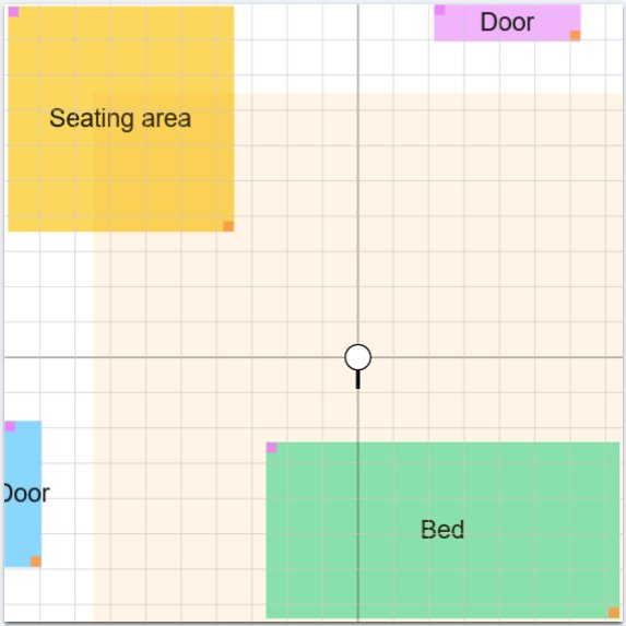
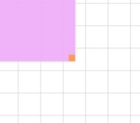
Several regions can be defined. The orange point at the lower right corner of a region serves as a point of reference for positioning the regions in space.

Regions should not overlap / overlap if possible, so that false reports are avoided. If overlays / overlaps are necessary and the fall and presence detection are defined differently, then the exclusion of the detection is rated more strongly than the inclusion. This is evaluated by the sensor.
Regions cannot be outside of space.
The regions can be used in the rules to report the occurrence of situations.
|
Parameter |
Meaning |
|---|---|
|
Name |
Name of the region. |
|
Kind |
Type of region. Depending on the type, predefined parameters are set. |
|
Width |
Latitude of the region |
|
Length |
Length of the region. |
|
x |
Deviation on the x-axis from the center of the sensor. Positive value to the right, negative value to the left. |
|
y |
Deviation on the y-axis of the sensor. Positive value to the front, negative value to the back. |
|
x2 |
Specification is determined automatically and is only used for checking. |
|
y2 |
Specification is determined automatically and is only used for checking. |
|
Fall detection |
This option enables fall detection for this region. |
Kind of region
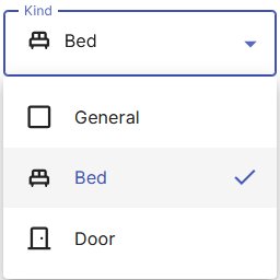
One kind can be defined for each region. When a region type is selected, parameters are set according to the manufacturer's specifications and can no longer be changed.

|
Kind |
Meaning |
|---|---|
|
General |
It is any region. All parameters can be set individually. |
|
Bed |
There is a bed in the region. Fall detection is switched off. This type of region must be selected to record vital data. In addition, the region must be in the monitoring area. |
|
Door |
The region defines a door. This causes another event to be displayed as soon as the resident crosses the door region of the room and moves away from it (either by leaving or entering the room). |
Monitoring bed
In order to use the function for recording vital data, the following requirements must be met:
- A region of the type "bed" must be created.
- This region must be in the monitoring area.
The monitoring area is marked in light yellow in the room shown and cannot be changed. This is within a radius of 1.5 meters in front of / around the sensor. This area is specified by the sensor.
The sensor evaluates the configured region. If all the information is correct, this region is used as a "monitored bed" and vital data is recorded. The status and vital data can be viewed on the sensor's data tab.
Limitations
There are the following limitations:
- If there are several people in the "Monitored Bed" region, vital data can still be recorded and displayed by the sensor, but a clear assignment is not possible.
- It is possible to create more than one region of the kind "Bed". The sensor evaluates the configured regions and decides which region is used as a "Monitored Bed". The status can be viewed on the sensor's data tab.
In all cases, misinterpretations and false alarms can occur.